| Home |
| Email John |
| Created 10/19/09 Last update 12/08/2010 |
Update - >1500 watts with a PFC board

Fact is, not many things in today's electronic world use high voltage DC. The result is that large capacity high voltage electrolytic capacitors cost a small fortune. If you build the induction heater described in this section, you will quickly discover that the filter caps for the rectified line power supply are probably the most expensive part.
The auto-tune unit that I'm developing for commercial sale requires fairly clean HVDC. When I costed the number of electrolytic capacitors that would be necessary to provide this clean power, I realized that they would cost as much as the rest of the machine combined.
Another problem with line rectified power supplies is that they present a low power factor to the power line. For a branch circuit with a given ampacity, that establishes a hard limit on how much power can be extracted from the line. Plus the rectification process introduces harmonics to the line that can cause other devices to malfunction.
Yet a third consideration comes into play. For a given load, power rises as the square of voltage. That indicates that if I increase the voltage on a given circuit, the power output rises rapidly. I'm using 500 volt FETs so why not take advantage of that property?
For all these reasons and more, I decided to implement a Power Factor Correction (PFC) power supply. A PFC draws power from the line in such a manner as to keep the power factor nearly unity. And since the unit switches at high frequency like a switch-mode power supply, much more reasonably sized capacitors can be used.
I prowled the major semiconductor manufacturer web sites and found the ideal chip in the International Rectifier IR1150 PFC controller. Not only was the chip ideal, but IR provided a reference design and application note. Even better, there is an on-line design calculator. Just plug in the desired output voltage and power level and it computes the reference design component values. Sweet.
I did a reference design for 385 volts and 1200 watts, modified the circuit a bit to suit my particular needs and ginned up a board. I decided to use the same IRF460 FET that I used on Maggie (the induction heater). That's way more transistor than the application required but that came in handy when I decided to exceed 1200 watts.
The centerpiece of the PFC is the flyback inductor. At this power level, a 200uH inductor capable of about 30 peak AC amps and up to about 6 DC amps is required. I tried a Digikey inductor that seemed to have the specs. With only an 80 watt load on the prototype, this inductor hit 300 deg F in under 10 minutes! Clearly something different was required.
I had been working with XFMRS.com on other aspects of the project so I commissioned a custom inductor. The inductor that they supplied works beautifully, getting only warm at full load. Unfortunately for you, they only sell in 100 pc minimum lots. Fortunately for you, you will be able to buy this inductor from us starting in December when XFMRS delivers.
Important note: If you use this PFC board to power your induction heater at high voltage, then you must increase the turns on the toroidal transformer. For 300 volt operation, I recommend starting with 40 turns and working down while monitoring the current going to the primary. Keep the current below about 8 amps to keep your FETs cool and comfortable.
Important note #2: You may buy a blank board and/or the inductor from us. Contact Garett for details. Also, if there is sufficient interest in this board, we may offer a complete kit. Since this board can power many things other than an induction heater (solid state tesla coil, tube amplifier, etc), it should be popular. Again contact Garett or me. Email addresses are on the heater's home page.

This board receives rectified but not filtered DC from an off-board bridge rectifier. It outputs anywhere from about 180 to 400 volts, depending on the setting of the feedback resistors and pot. This is the entire power supply except for the bridge rectifier. No other capacitors or other components are needed.
Here is the schematic for the device. The ExpressPCB CAD file is here.

The PCB layout. The ExpressPCB CAD file is here.

This photo tells the story. A power factor of 0.96. Since 1.00 is perfect, it doesn't get much better than this. IR, ya done good!

Another closeup of the board showing how I hacked in the voltage adjustment pot on the prototype board, and also showing more details. The pots are integrated in the production board that we sell. There are spaces for two pots on the board. Since you'll porbably not be switching voltages, simply don't populate one space.

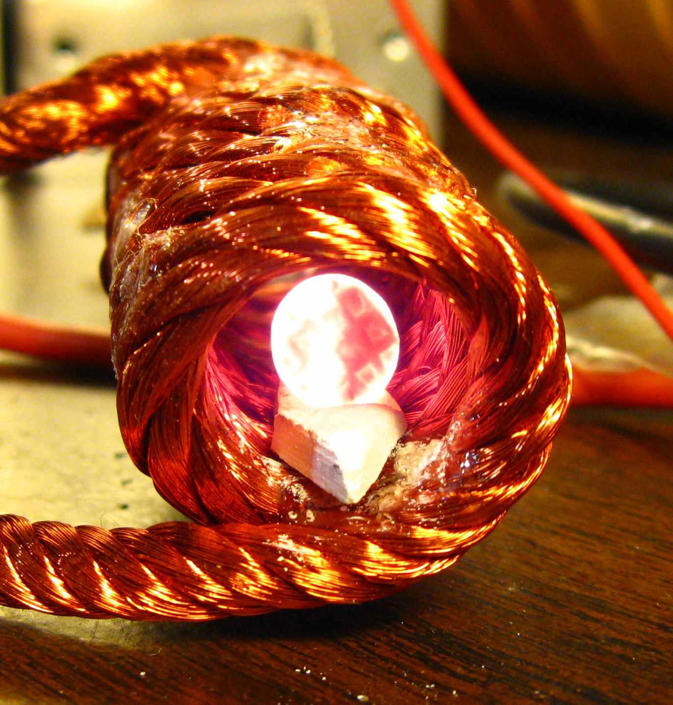
The Result - this short video shows Maggie running on the PFC with the voltage set to about 300 volts. A 10mm neon electrode is in the work coil. Listen carefully for the click of the switch being thrown. Maggie lights up this 'trode like a light bulb. I didn't measure the power but I estimate that it is north of 1500 watts.

Here's what the neon folks have been waiting for. A 15mm electrode being heated in a C-coil. With this type of coil, it can simply be held up to the electrode instead of having to be mounted around it before processing. Note that we're still working on making pretty C-coils. This one is functional but it ain't pretty :-)