| Home |
|
Email John
Email Garett |
| Created 02/25/2014 Last update 03/08/2014 |
HEI Ignition Coil-Based X-ray Tube Driver

Update 03/03/2014. - I have started a new mailing list for the discussion of this project and other things such as non-medical imaging and fluoroscopy having to do with X-rays that are not welcome in our old home. Subscribe here and post to x-ray@neon-john.com.
I recently discovered a mailing list for nukes like me who enjoy working with nuclear radiation. In discussion it came up that many of the members would like to get into X-ray photography and other activities involving X-rays. Many of those people have or can get X-ray tubes but lack anything to drive them with. I have several tubes including this very large one and am in the same situation.
The requirements are pretty tough. Anywhere from about 20 to 150kV and from a few microamps to a few tens of milliamps. And for doing things like studying the effects of radiation on materials, the power supply should be able to run for an extended period of time.
We talked some more and I announced that I would design a suitable driver. Fast-forward about 3 weeks until now. The prototype is finished and the printed circuit boards are being made. We (Fluxeon.com) are going to sell bare boards and if there is a demand, assembled and tested boards. The boards are designed to fit into small aluminum extrusions that we also sell.
Before we go on, let's do some house-keeping. I need to make sure I'm addressing the appropriate audience. Lawyer-repellant, you know. So without further ado
- First, you acknowledge that you are of suitable age and maturity to be playing with dangerous things. If you're not old enough to vote then please close this page and go away
- We are all big boys and girls and we can judge risks and either mitigate them or accept responsibility for our actions. If you don't agree with that statement then leave.
- This project involves dangerously high voltage, current and nuclear radiation. You acknowledge that you either know what you're doing around these things or that you will learn BEFORE beginning any construction. If that statement doesn't agree with you then leave.
- If you hurt yourself or someone else then you agree to take responsibility for your own actions and will not expect me to accept any blame for your irresponsibility. Again, if you don't agree then leave.
- No warranty as to the accuracy or correctness of this article is given. If you expect any sort of guarantee then leave.
OK, you're still with us. Good. Let's jump right in. This driver, which is based around 4 GM DR37T HEI ignition coils, is capable of reliably generating up to around 150kV and about 10ma of current (but not both at the same time) when immersed in mineral oil for cooling and insulation. Electronically, the circuit is similar to the quasi-resonant power supply inverter. The coil's inductance is charged with magnetic energy until the current reaches the setpoint. At that point the IGBT is turned off for about 20uS and the flyback energy is directed out the high voltage terminal of the HEI coil

This is the coil. I show a NAPA coil because in this tiny little town I live in, that's the only brand available. It cost me more than $30 with tax. Rockauto.com has them for $11.30 when I checked last week and discountautoparts.com has them for $13.75. You'll need 4 each.


OK, so let's get a schematic on the table so we can start a discussion. Just click the image to the left to download a PDF version of the schematic.
Let's take a quick tour. We'll start with IC1, a CD4047 multivibrator, in this case configured as a non-retriggerable one-shot.
When power is applied, the 4047 comes up in the reset state. The *Q output is high. This drives IC2 which in turn drives the gates of up to two IRG7PH42UD1 IGBTs. Only one is required but I included space for two just in case.
This IGBT is a beast with an absolute max rating of 1200 volts and 80 amps. It turns on and current starts building from the HVDC source (rectified line voltage), through the coils, through the current shunts and to circuit common.
NOTE: This is a line-operated device and as such the entire PCB is at line potential. You MUST use isolation transformers for your safety. We'll cover that a bit later.
The current rises as fast as the driving voltage and the coils' primary inductance will allow. Op-amp IC4a, a very high speed single supply amp looks at the shunt with a gain of 22. The output of that opamp drives IC3A, a moderately high speed comparator. When the voltage (current) reaches the setpoint dialed in by the pot R17, the comparator output goes high.
The leading edge of this transition is applied to the +trigger input of the 4047 which triggers it active for the duration set by C5, R2 and the pot R3, normally around 20uS. This causes the *Q output to go low which turns off the gate driver and thus the IGBT.
The collapsing field in the coils generates a high voltage flyback in both windings in proportion to their turns ratio. The secondary is the one we're interested in. The energy stored in the core's air gap appears as a high voltage pulse on the secondary. It is proportional to how much current was flowing and how fast the current is stopped.
The snubber capacitor, which is located on the coils under the oil bath (see external connection diagram) is a high quality pulse-rated CDE film capacitor. Part #940C16P15K-f, available from Mouser as Part # 5984-940C16P15K-F . It is VERY important not to substitute any other capacitor for this one. It must handle very high current and very high voltage with very low ESR.
The capacitor slows down the field collapse. This results in a lower voltage but a longer lived pulse - what we want for driving an X-ray tube. The transistor is also equipped with a Panasonic ZNR14621 transient voltage suppressor. This TVS starts conducting at about 1000 volts and is designed to protect the transistor if the capacitor fails.
If this was a pure quasi-resonant design, I would have another comparator detecting when the current dropped to zero and it would be driving a flip-flop. This would allow the current to be turned back on the instant the current dropped to zero.
The problem is, this is a touchy circuit, especially with all the high voltage flying around so I decided to KISS and simply turn the coil off for a set period of time. Since this time can be adjusted by R3, the user can tune the off time to be almost as brief as with a fully quasi-resonant design but without all the headaches.
I'm including the Eagle files here but please don't rush out and use them to have a board made. This board has not yet been tested! Plus you'll be able to get them from Fluxeon in a couple of weeks for about $12.
The repetition rate is dependent on both the driving voltage and the current setpoint. In general, you want to adjust the setpoint and the timing pot R3 so that the driving waveform on the gate of the IGBT is as close to a square wave as possible. When that is achieved, the current is turned back on the instant the coils discharge and because of the high driving voltage the coils recharge very rapidly.
This video shows you the sound and fury of the unit running with about 50 AC volts incoming. At 120 VAC in, one really needs hearing protection because of the howl of the cores' magnetostriction.
The photo at left shows what the result of the arc in that video did to some high temperature refractory board. There was about 500 watts input to the system. Quite a lot of power in a small place.

This photo shows the breadboarded design. From left to right, the LMC6482 op-amp, the 4047 one-shot, the LM393 comparator and the MC33152 dual gate driver.
This shows the transistor, coil, capacitor (white object, upper left) and one of the ignition coils. The PCB design has the transistor and TVS mounted on the board while the capacitors (one for each 2 coils) is mounted directly to the coils. The heavy current-carrying leads should be at least 14 gauge (I use silver-plated teflon insulated wire with 1000 volt insulation rating. They should be twisted to minimize radiated EMI.

This shows the coil connection. The two upper pin are connected internally, as are the lower two. The HVDC comes into the coil through the lower pair. The upper pair connect to the IGBT. It's important to get this polarity correct, as it determines the polarity of the output pulse. The pulse must be positive if you're driving a hot anode X-ray tube.

This is the drawing of the external connections. Again, click the thumbnail to download a PDF. The drawing is simple enough that it doesn't really need any explaining.
One very important thing is that the length of wire connecting each coil's primary must the the same for the coils to properly share current. I cut lengths of 14 gauge teflon wire of equal length, twist them all together along with the incoming lead and red wire-nut the whole affair. It will be under oil so that will work fine even with the high voltage involved.

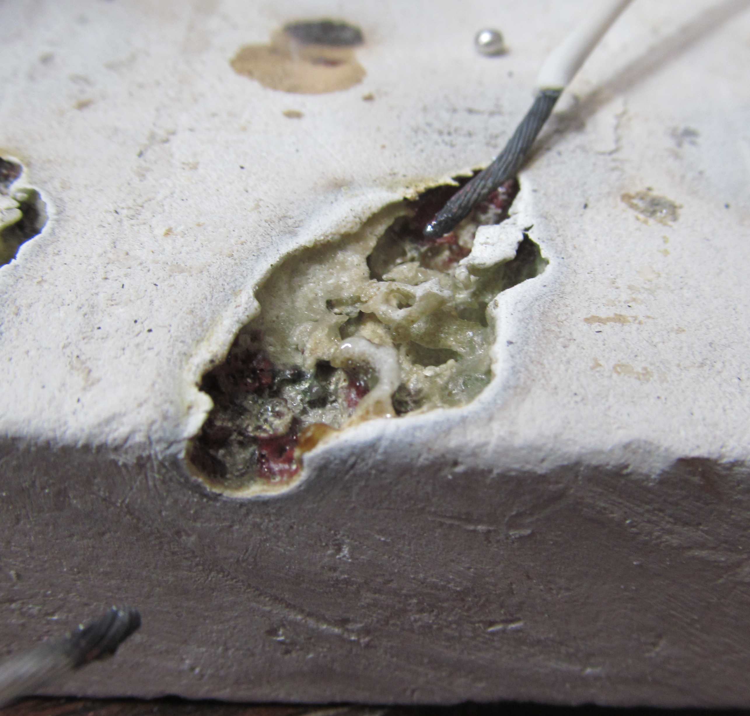
Finally, who can resist some destructive testing :-) OK, so I threw the whole 120 VAC output of the driver at just one coil. Just curious. Took about 3 minutes of arcing to fail.
The failure was anti-climactic. Just a gentle pop, a little smoke and that white ooze. And amazingly enough, even though wire ends are visible in the ooze, the coil didn't quite sparking.
This gives me even more confidence that a set of 4 oil-immersed coils will run continuous duty, even at full output.
Board Initial Setup

Once you have the board constructed, it needs to be set up for initial operation. These instructions will get it running and then you can adjust it for the desired voltage and current as need be.
Set the "off interval" pot R3 to the mid-point. Set the current limit pot R17 to about 3/4. Arrange the high voltage lead as shown at left at least a foot away from other object. This "corona dummy load" provides a bit of load to the coil and prevents very high voltage excursions.
Connect your scope to TP1. This test point is an amplified version of the current waveform across the shunt. .
Apply 12 to 24 volts to the board and adjust R17 if necessary to get the oscillation to begin. Once the oscillation begins, you may turn down the voltage if you desire to reduce the magnetostriction and spark gap noise.
In the photo below, the two red lines show the effect of the "off interval" pot R3. I used fixed resistors in the prototype and so the off-time is much too long. Adjust R3 until the time interval is about the distance between the red and green lines. If operation is not smooth then add just a bit more time. The shorter this time interval, the faster the rep rate for a given input voltage and current setting.
Waveforms


These two scope shots show the most important waveforms. In each shot, the upper trace is the shunt current directly off the 1 ohm shunt and the bottom trace is the high voltage output pulse measured via a Tek P6015 high voltage scope probe. Typical of the over-engineering of the Tektronix of old, the probe is rated for 45kv peak max but so far it has functioned properly at 120kV. Of course I was NOT holding the thing!!!
The top trace is with the incoming DC set to about 12 volts. The output voltage is about 40kV, just what one would expect from an HEI coil.
In the second photo, the current setpoint has been turned up. As you can see the current rises much faster. The output pulse is about 60kV. Turning the current up at a given voltage slows the rep rate. A higher incoming voltage causes the repetition rate to increase. Thus you can adjust the two to maintain a given voltage at higher or lower output current levels.
With 120 volts in and a bit higher current limit, the wail is like a banshee, running at between 2 and 3 kHz.

This shot shows the IGBT collector voltage. Notice how the waveform is almost identical to that of the secondary output above. This photo is of the output with no sparking occuring.

This is the same connection as above but this time the secondary is being allowed to arc. Notice that the peak voltage is much reduced but that the event lasts much longer. Something in-between these two is what you'll see with an X-ray tube connected. The tube will load the secondary so that current flows longer during the off period. That's what we want. Current flow = X-ray production.
Operation

This vid shows R17 being turned to smoothly vary the voltage from about 20kV to about 80kV. This is with 28 volts in.
As indicated, the unit should be turned on and off by switching the 15 volt power supply to the board after the HVDC is applied. Applying 15 volts first can lead to a very high voltage initial pulse which can destroy the transistor.
There seems to be some concern on the XRL mailing list that this driver is too powerful and that it would not be useful for such applications as XRF. Nothing could be further from the truth.
The scope shot at the left (yellow trace - IGBT collector, blue trace - high voltage outptu) shows the driver operating smoothly at just a touch over 20kV and 28 volts in.
Notice that the rep rate is 28kHz. Nice smooth high frequency output. If the input voltage is taken lower, say to 12 or 14 volts then the driver can go to 10kV or less. This is a truly versatile driver.
Oil Immersion

A tall square or rectangular glass jar is preferred but resources are slim around here so this is what I found at Hobby Lobby. It is adequate but it could be a little deeper.

I added some stained glass jewels to the bottom. The space the coil a bit off the bottom and help to hold them in place.

These two photos show the treatment I gave the coil (all 4 will get the treatment when they arrive) before immersion. I coated the high voltage tower with Shoe Goo (polyurethane resin before heat-shrinking some tubing on the tower. This is mainly to hold the cable upright and provides minimal dielectric qualities.
I Shoe-gooed the places where flash-over is likely to take place. Finally, I glued the snubber capacitor in place with Shoe goo. It is vitally important that this capacitor not become disconnected, thus the adhesive.

This is the mineral oil that I used, purchased from Tractor supply. It's a bit expensive at $20/gallon but it's convenient and easy to buy.
Before pouring it over the coil, I put it in a pot and heated it to 250 deg and left it for a couple of hours to dry and de-aerate it. A considerable number of bubbles formed, indicating that this needed to be done.

Here is a single coil in the oil. I placed the coil in the oil with the high voltage tower down and sloped the assembly to the left. That is to provide more immersion dept for the high voltage part.
The cable used is super-limp neon GTO wire from West Coast Custom Designs. Their website is kinda hoky but they're good people.
The cable is rated at 25kV. Thus it provides little insulation to the 100+kV this generator is capable of. The insulation does cut down on corona losses and ozone generation which is important.
There is a silicone-insulated neon cable that is rated to 45 kV. I have yet to find anyone who will sell cut lengths and a whole box is expensive. I'll keep looking.
When this cable is routed, it will be suspended on pieces of that pink electrical fiberglass board. That is available from McMaster-Carr.
After all 4 coils are in place and wired up, a circular cover of the same pink fiberglass board will be cemented on top of the bowl to hold the wires in place, to keep out dirt and moisture and keep the oil in.
Safe Working Environment
Practically everything I work on is line powered and so my lab is set up to safely work on line operated equipment. I have isolation transformers not only for the device being worked on but also a separate one for the test equipment. Let's take a tour.

Here's my cheap Chinese 5KVA variac. Yeah, it's cheaply made and yeah, the voltage sags too much under load but it serves my purpose.
This is the core of my safe working environment (not counting the cat hair, of course :-). On the left is a 5 KVA Topaz Ultra-Isolation transformer. This is the very top of the line. Topaz advertises that there is only 5pF of capacitance between the primary and secondary. What I know is that I've touched a hot circuit before and only gotten the barest minimum of a tingle.
On the left is my "Dead Man's" control box. It contains a 24 volt transformer and a 30 amp DPDT contactor. The contactor is energized by a foot switch. The spring is pretty strong so the only time the DUT is energized is when I'm positively pressing the pedal.

The foot switch. This is a very high quality switch. No skimping here. And because it switches only 24 VAC, there is no possibility of a shock from a fault in the switch. The entire control box is powered from the isolated side of the Topaz.
Radiological Safety
As I said in the introduction, an X-ray tube driven by this device will generate enough X-rays to be very harmful. It will produce a beam strong enough to deliver burns in minutes and lethal in hours if your whole body is exposed.
Worse, exposure that causes no outward symptoms will do somatic damage (genetic damage, mutations, Leukemia, cataracts and so on.) You simply must know what you're doing before you power up that tube.
As a nuclear professional, most of what I see on the net makes me cringe. Tubes being operated bare with no shielding. Tubes being operated in a spare bedroom shop where other people in the house are being irradiated. Do not do what you see on the net.
My lab is underground in an isolated place way back in the mountains. I live alone. I have the proper instruments and knowledge to use them to prevent exposure. I suggest you do the same. Eventually I'll do a whole page on radiological safety but let's get in the bare essentials now.
Since you've spent the time and money to build the driver, let's stop for awhile and learn the basics of health-physics.
The first thing you need to do is download the Radiological Health Handbook. Then study it.
Next buy a copy of "Introduction to Health-Physics" by Herman Cember. Yeah, it costs a few bucks. So does cancer therapy!
Next pledge to Never ever expose a living thing to radiation and that includes yourself. Every budding radiographer wants to take an X-ray of his hand. Don't do it. Practice ALARA (As Low As Reasonably Achievable). Here's what happens when someone figures just a little bit more hand exposure won't hurt anything. Notice the dates between the photos. A year or more of festering wounds and permanent disfigurement.
The Health-Physics Society has tons of literature, much of it aimed at the layman.
Another good place is the ICRP. Their older reports are quite reasonably priced and many have been released to the net. They are considered the world authority on radiation protection.
This is enough to get you started. But don't be afraid to ask questions. If I can't answer them I can direct you to someone who can.
There is a mailing list on Yahoo called xrl@yahoogroups.com. This is the list of enthusiasts I mentioned earlier. Lots of experts there.
update 03/01/2014. This project has caused a great schism in the ranks because some think it's "too powerful". The list owner asked me to take this project elsewhere and at the same time added a large pile of new restrictions on what people could do. Basically little more than low power XRF.
Therefore I have set up a new mailing list. x-ray@lists.neon-john.com. Subscribe here.. This list is open to any topic concerning the non-medical uses of X-rays. It is a private list and no archives are kept. I think that xrl@yahoogroup.com will become primarily a low power XRF group and this new one will handle the rest of the discussions.
While we're talking about safety, remember that the high voltage energy this device generates can kill you dead in a heartbeat.
Finally, a tip to the wise. Don't brag about what you're doing. Don't even show it to friends lest you attract the attention of your state's Bureau of Radiological Health. Be safe and be silent.
yet to come - 4 coil operation, final connections and configuration and the bill-of-materials.