|
Citi Motor Repair
 motors repaired since 05/27/07
|
The motor in my Citi was burned
out. The simple contactor-type controller puts a severe load on the
motor when starting from a stop. I'm sure that this load is what
damaged my motor.
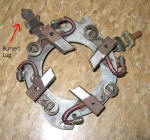
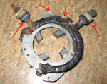
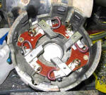
Once inside the motor, I was surprised that it had lasted as long as it did.
The photos to the right show the brush holder as it came out of the motor.
The previous owner had tried to fix the damage without satisfaction.
Considering that this motor gets hit with >1000 amps at startup, it's
amazing that those little conductors lasted as long as they did.
I took one good look at this brush holder, gave it last rites and went about
finding a new one. Fortunately this was a common GE motor and so
repair parts are available. I ordered one from my friendly local
electric motor shop. |
 |
The new holder arrived but it did not include
the interconnect bus bars. I ordered them. When they came in,
they were even lighter than the originals, consisting of nothing more than
about 8 ga stranded wire with lugs crimped on the ends.
At that point I realized it was time to do some improvements. I
decided to bring out a lead for each brush and to connect them externally. |
 |
Here is the new holder mounted in the end bell.
It is not nearly as substantial as the original but so far it has held up
well. |
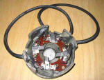
| This photo shows the end bell with the new system
almost finished. Each brush gets a length of 4 gauge 125 deg C motor
hookup wire. Details follow. |
 |
|
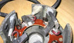
| This photo shows the details of the brushs and
new wiring. Each lead is fastened rigidly to the end bell with wedges
and epoxy. The lugs are
crimped and then (after this photo was taken) soldered. |
 |
|
| The first step to fastening each lead is to
isolate it from the bell and fix it in place. For this I used popcicle
sticks. |
 |
|
| Next Rectorseal kneadable epoxy is forced in and
around the wire hole. This type of epoxy can be worked with gloved
fingers and smoothed with a wet finger. |
 |
|
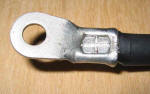
| Here is a photo of a properly crimped lug using
the hammer crimper. |
 |
|
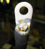
| Here is a properly crimped, soldered and heat
shrunk terminal, ready for installation. |
 |
I use the Kester #1544
flux, available here, for
all my soldering work. The difference this flux makes with hand
soldering has to be experienced to be believed.
I soldered the lugs using a small butane torch to heat the lug.
Conducted heat warms the cable until solder will wick. A cold rag
clamped tightly around the cable just below the lug stops the solder from
wicking back and making the cable stiff and fracture-prone. |
| Here I'm doing a trial fit to check for
clearances. Everything's fine. |
 |
|
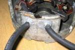
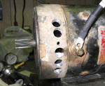
While I had the motor apart I added some cooling
holes to the front of the motor. This made a dramatic difference in
the operating temperature even without a fan. I'll be adding forced
air cooling when I do the 72 volt upgrade.
These holes are covered by a shroud that vents into the car's interior to
keep out road dirt. |
 |
|
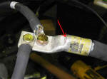
| This photo shows how I connected pairs of brush
leads together. The big lug is hammer-crimped and soldered after this
photo was taken. Solder can be fed through the inspection hole
(arrow). |
 |
|
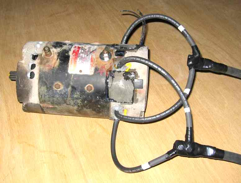
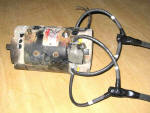
| Another view of the finished motor, ready to be
installed. Note that I have waterproofed all the inspection covers
with RTV. One cover remains open and is connected to the inside of the
car with flex hose to provide cooling air. This hose will get a fan
later. After I installed the motor and verified clearance and final
orientation of the wires, I wrapped each junction with 3M self-vulcanizing
tape, a layer of fiberglass tape and an outer layer of Scotch 33 electrical
tape. This makes a completely waterproof and abrasion resistant joint.
|
 |
|
| This modification/repair significantly improved
the performance of this motor. The old interconnects must have been
dropping a lot of voltage. The project is a complete success. |
|
|
|
|
|


