| Home |
| Email John |
| Last update 12/09/2010 |
Cordless Battery Charger (TM)
 Custom Search
Of course I'm not the first to think of driving a car alternator with a gas engine. But from what I can tell, I'm the first one to do it correctly.
To be able to force as much energy as rapidly as possible into a battery and still not fry it when it is charged, a smart multi-part charging scheme is required. The best known is the 3 stage scheme known as the "bulk, absorption, float" algorithm. The three parts are as follows:
The bulk stage involves feeding the battery with current limited power. The voltage is whatever the battery terminal voltage is. The current is either limited to a set value or is the maximum the charger can produce. As the battery accepts charge, it's terminal voltage rises. When it reaches a certain voltage that depends on the battery chemistry and temperature, the bulk stage ends. Assuming the charger is capable of 1C or better charging current, this stage lasts only a short while, usually less than an hour.
The absorption stage is a constant voltage regime. Constant voltage, in the nominal range of 14.2 volts, is applied to the battery. The current is whatever the battery can accept as it absorbs charge down deep in the plate materials. The current tapers off as the stage progresses. When the current reaches a designated minimum, in my case, 2% of the initial current, the absorption stage is over. This stage lasts from 3-4 hours regardless of the battery size.
The float stage involves reducing the voltage to just below the gassing point, around 13.8 volts, to finish the charge. This is usually a timed stage but can continue indefinitely if desired.
- The bulk stage represents from 50-70% of the total charge.
- The absorption stage represents from about 70% to 90% of the total.
- The float stage accounts for the rest.
In the early 90s I designed my first CBS to implement this charge algorithm
by controlling both the field excitation and the throttle. I used a
small 2-stroke engine, a small alternator and a home-made control circuit.
This CBC would produce 60 amps during the bulk stage and weighed only about
12 lbs.
I made a few of these, enough to see that there was a demand. Several
things happened that prevented me from commercializing this design.
Eventually I put the design on my file server (no web back then, files were
served up via email requests.) A couple years later Coleman came out
with the Mighty Mite combination generator/charger that was an almost exact
copy of my design. Did they use mine? Who knows.
In about 2000 I bought a motorhome and started camping again. I do not
like RV parks or crowds so I generally "dry" camp on unimproved flat spots.
Obviously there is no power available. I like my conveniences such as
plenty of light, music, etc. That means that a means to recharge the
rig's batteries was needed. Enter CBC-II.
The goals for CBC-II were as follows:
- 150 amp output. House batteries to recharge in a couple of hours.
- Smart 3 stage algorithm.
- Charge rate varied by engine speed to minimize noise.
- Auto-shutdown at the end of the charge cycle.
- Lightweight and man-portable without straining - <35lbs.
CBC-II as it stands today meets all those goals except the auto-shutdown.
That is coming in the next generation of controls.
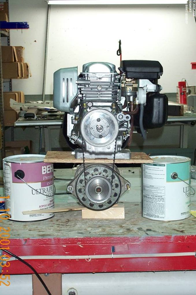
Following are some photos of the work in progress. Unfortunately this
part of my web is incomplete for now. I
have not properly kept up with the photography. That will change as
the round tuits become available. Meanwhile, enjoy the pix.

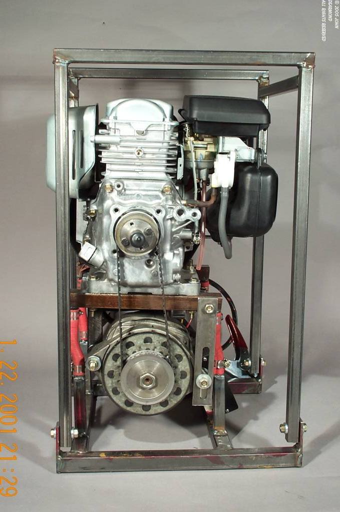
I learned that this engine has a problem throwing the timing belt in cold weather. Honda has a retrofit kit that keeps oil from building up between the belt and pulleys. My solution is to use the 5w20 Mobil 1 synthetic oil. That also gains me about a half horsepower from reduced windage losses.