| UPDATE 06-04-06 Click Here |
| John G's BBQ |
| Email John |
| Last update 02/17/2009 |
Front Brakes
brakes fixed since 05/27/07
These parts are available from most any golf cart supply company. Here are the ones I've looked at:
LVS Sales
Advanced Electric Vehicle Center
Parts
4 Carts, AKA Alabama Cart Sales <-- where I bought
Cart Zone
Glenn at Assembled Parts also stocks brake parts.
LVS sales had the best price but the rather rude phone answerer sent me elsewhere. Parts 4 Carts doesn't have an E-store so you have to phone in the old fashioned way. Nonetheless, they got me my parts practically overnight.
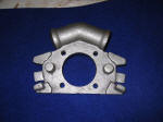
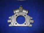
Here are the parts you need: (click images to enlarge)
 Back
Back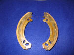
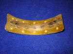

There has been quite a bit of confusion on the past about part numbers. These brake parts were originally Bendix brand. Now they're made in India. The numbers quoted above are used by all the dealers I talked to so they must be some sort of aftermarket standard now. In any event, you can always reference the photos above when inquiring of another dealer.
The spider has been variously referenced as Bendix part number 884126 and Ez-Go part numbers 19038-G2, 21086-G1, 3959G1, 1730036, 21086G1 and 1701309 plus some Cushman part numbers. In my experience, quoting these numbers only confuses things. The 4 digit number above was immediately familiar with everyone I spoke to.
A rebuild kit is available for this spider but mine was so corroded that
I decided to buy the whole new assemblies.
Note the differences in the retracting spring retainer boss. The old one has a lip while the new one uses a recess. Both seem to work.
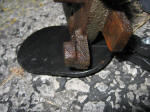
Bendix spring retainer boss
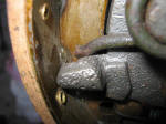
Indian-made spring retainer
Following is a step-by-step photo procedure for the overhaul of one front brake assembly. Note that the left and right sides are the same.
Step 1: Remove the wheel and drum. Back off the adjuster if necessary to let the drum release. The adjuster is a toothed wheel (see below) that can be turned with a screwdriver after removing the rubber access plug.
The drum may be stuck to the axle if the assembly is rusted. DO NOT try to pry between the backing plate and the drum! The plate is plastic and will break. First try tapping the rear of the drum with a soft face (brass) hammer. If that fails then a 3 jaw gear puller can be carefully used. Do not force things, as the drum is easily warped and replacements are hard to come by. Heating the hub around the studs might also help.
If all else fails, pop the grease cap, remove the bearing retainer nut and remove the hub and drum as an assembly.
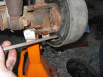
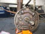
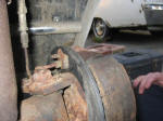
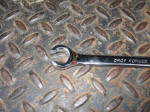
Brake line nut wrench, also known as a "flare nut wrench". Note how the wrench surrounds the nut to the maximum extent possible.
Step 3: Remove the retractor springs. I removed mine by grabbing the small end that rests on the spider boss with channel locks, then twisting and pulling. Note the small difference between the two springs. Don't mix them up.
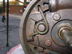
Left side
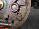
Right Side
Step 4: Remove the adjuster and spring from the bottom of the shoes. Needle Nose pliers are adequate to remove this spring. Note the orientation. Note how the spring also keeps the adjuster from rotating by itself.
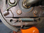
Step 5: Remove the shoes. Note the orientation of the yellow anti-rattle clips. While not vital, these clips help damp brake squeal and rattle.
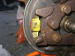
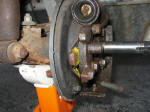
Step 6: Remove the 4 bolts holding the spider to the spindle. If the backing plate is greasy as mine was, remove it and clean it to prevent the grease from getting on the new shoes.
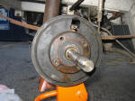
Step 7: Remove the bleeder plug and brake line entrance protective cap. Place the new spider on the spindle. Start the brake line nut threads into the spider. Finger tighten the nut. Mount the spider with the 4 bolts but do not tighten them. Finish tightening the brake line nut and inset the bleeder plug finger tight, then tighten the 4 bolts.
Step 8: Place the yellow anti-rattle clips on the new backing plate and slide the new shoes on. Note that the large rounded end of the shoe goes against the piston.
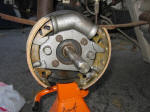
Step 9: Place the end of the retracting hair spring in the diagonal slot at the top of the shoe. Place the coil of the spring on the round boss and tap it in place with a hammer and socket. The fit was tight on mine. Using a screwdriver, force the spring tang up and over the boss. Make sure the tang seats in the recess at the back of the boss.
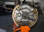
Step 10: Screw the adjuster all the way in. Fit it to the brake shoes as shown to the right. Note the orientation relative to the adjusting slot in the backing plate. The notched wheel should align with the slot.
Using needle nose pliers, install the retaining spring.
This completes the brake assembly.

Step 11: Re-install the hub. Clean and pack the bearings if necessary.
Make sure the axle is clean. Apply a thin film of axle grease to the axle and to the seal seating area back next to the backing plate. Just a tiny bit is enough. Excess will get on the shoes.
Slide the hub onto the axle, apply the washer and nut and tighten lightly with a wrench.
Back off until the next slot in the castle nut aligns with the cotter pin hole.
Insert a new cotter pin and bend it over.
Partially fill the cap with axle grease and tap in in place with a soft face hammer. GENTLE taps will do. The hub should rotate with little to no drag. If there is more than a very slight drag then either the seal in back is dry or the nut is too tight. Loosen the nut and try again.
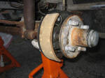
The completed assembly, ready for the drum.
Step 12: Place the drum on the hub. It should fit freely over the shoes. Turn the adjuster until the drum drags a little. At first this is most easily done by sliding the drum back off and turning the toothed wheel with your fingers. After the drum starts to get tight when sliding on, reach in through the adjustment port on the back and turn the wheel with a screw driver.
When properly adjusted with new shoes, there should be significant drag on the drum. Being barely able to turn it without straining is about right. The shoes quickly wear in to fit the drum so the drag will go away inside the first mile of travel.
Bleeding the Brakes
It's easiest to bleed the new cylinder before installing the wheel and tire.
Step 1: Get a "one man bleeder" kit like the one pictured to the right. This kit costs under $10 and makes bleeding trivially simple. Follow the enclosed instructions for connecting it to the bleeder plug.
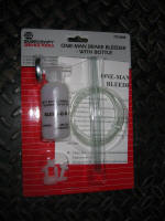
Step 2: Loosen the plug about a half turn.
Step 3: Make sure the master cylinder is full of fresh fluid. Slowly push the brake pedal while watching the clear tube of the bleeder kit. When the pedal reaches the floor, slowly retract it and repeat as necessary.
Normally one would bleed until there are no bubbles visible in the bleeder line. In this case, since the brake fluid in the lines is likely decades old, continue pumping the pedal until new fluid comes through the bleeder line. Make sure the master cylinder remains filled with fluid.
Step 4: Snug the bleeder plug (do not force!), remove the bleeder tool and fit the protective rubber cap that came with the new spider.
Step 5: Check the shoe adjustment. Re-adjust if necessary to get significant drag on the drum. Replace the access slot rubber plug. If the plug is missing, cover the hole with good duct tape or even better, aluminum tape.
Step 6: Mount the wheel. Tighten the lug nuts snugly but do not force. Do not use a power impact wrench. The hub metal is fairly thin and can easily be distorted. This will distort the drum, resulting in lumpy and jerky brake action.
Step 7: Drive the car a mile or two while lightly applying the brakes. Alternate on and off the brakes at about 1 second intervals. This process seats the shoes and forms the initial finish. Do not overheat the drums at this point.
Step 8: If the pedal travels more than about 3/4" before the brakes apply, adjust the shoes as before. This is usually necessary, as the shoes quickly wear in to fit the drum.
Top off the master cylinder if necessary.
You are now finished.
