| Email John |
| Last update 02/17/2009 |
Front Brake overhaul Update
The most important thing I've learned is that the indian-made spiders are junk. Apparently tolerance and finish and finish are new concepts to the indians.
The lack of finish or control of dimensions resulted in one wheel that would lock up solid whenever any amount of brake pressure was applied. It would stay locked up until the vehicle was allowed to roll backward.
After taking the wheel and brake drum off several times, I decided to pull the whole brake assembly off, take it back to the shop and look things over in an orderly manner. One thing quickly became evident - again - and that is, NEVER THROW AWAY OLD PARTS. At least until you're absolutely positively sure that the new parts work OK.
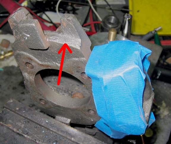
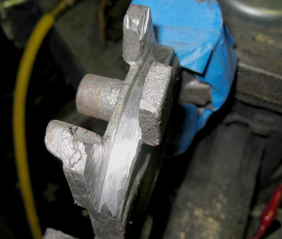
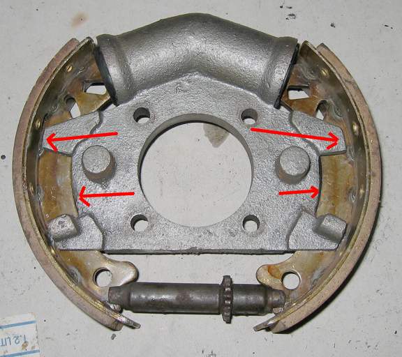
The basic problem I found was that the critical shoe back-seating radius on the spider AND the length of the guide tangs were so far off that the shoes were jacked up such that whenever brake pressure was applied, the shoe wedged between the drum and the cylinder and locked the wheel.
The solution was to machine the spider to more suitable dimensions. The old OEM spider provided known-good dimensions. Ideally the spider would be chucked up in a lathe and the important radii turned to perfection. Lacking such luxuries, I substituted the next best thing - an angle grinder, a wheel of suitable width and a stable hand.